Excess 3 Adder Circuit Diagram
Bcd code excess convertor lab digital click Adder circuit schematic diagram Full adder – electronics post
Complete circuit of the full adder using the newly proposed design. The
Complete circuit of the full adder using the newly proposed design. the Block diagram of bcd to excess 3 code converter the bit combinations Adder subtractor logic
Solved 4. (a) construct a 4-bit binary adderisubtractor
Adder excess binary construct bcd converterEdacafe: power, accuracy and noise aspects in cmos mixed-signal Bcd excess assignedFull-adder circuit, the schematic diagram and how it works – deeptronic.
Solved build the adder-subtractor circuit from page 18 fromAdder combinational parallel adders circuitverse Excess bcd logic code circuit digital geeksforgeeksDiagram excess bcd code logic converter using gates circuit precautions block ic.
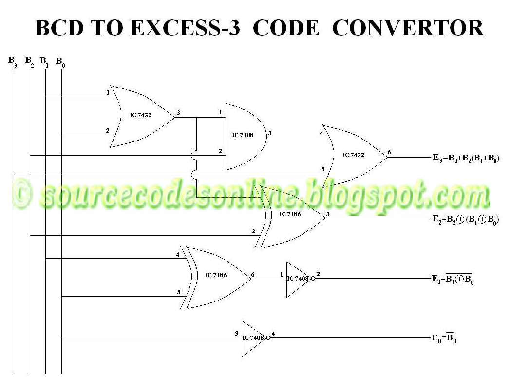
Draw a neat circuit of bcd adder using ic 7483 and explain.
Bcd to excess 3 code convertor in cs1206 digital labFull adder circuit: theory, truth table & construction Adder cmos circuit diagram transistor fa using 28t transistors implementation edacafe transmission gate power fig phdthesis www10 bookAdder circuit construction binary circuits ibm sourav gupta.
Adder bcd 7483 using ic diagram circuit block draw neat sum case3 carry but explainDigital logic Adder logic half implementation.
![Full Adder Circuit: Theory, Truth Table & Construction](https://i2.wp.com/circuitdigest.com/sites/default/files/projectimage_tut/Full-Adder-Circuit.png)
![Full-Adder Circuit, The Schematic Diagram and How It Works – Deeptronic](https://i2.wp.com/www.deeptronic.com/wp-content/uploads/2019/09/full-adder-circuit-300x131.png)
![Complete circuit of the full adder using the newly proposed design. The](https://i2.wp.com/www.researchgate.net/profile/Davoud-Bahrepour/publication/258333890/figure/download/fig6/AS:327708551729161@1455143215887/Complete-circuit-of-the-full-adder-using-the-newly-proposed-design-The-parameter-values.png)
![DeldSim - BCD to Excess-3 code converter using logic gates](https://i2.wp.com/www.deldsim.com/circuit_diagram/39.png)
![Draw a neat circuit of BCD adder using IC 7483 and explain.](https://i2.wp.com/i.imgur.com/Jm8QhB3.png)
![Solved Build the Adder-Subtractor circuit from Page 18 from | Chegg.com](https://i2.wp.com/media.cheggcdn.com/media/c42/s890x607/c4201110-785f-43c2-b86e-f12b8df8f400/phpG3FLSj.png)
![EDACafe: Power, accuracy and noise aspects in CMOS mixed-signal](https://i2.wp.com/www10.edacafe.com/book/phdThesis/Image1254.gif)
![Block Diagram Of BCD To Excess 3 Code Converter The bit combinations](https://i2.wp.com/www.researchgate.net/publication/319456209/figure/fig2/AS:558408161075200@1510146288802/Block-Diagram-Of-BCD-To-Excess-3-Code-Converter-The-bit-combinations-assigned-to-the-BCD.png)
![Full Adder – Electronics Post](https://i2.wp.com/electronicspost.com/wp-content/uploads/2015/04/311.png)
![Adder - Classifications, Construction, How it Works and Applications](https://i2.wp.com/electricalfundablog.com/wp-content/uploads/2020/01/Full-Adder-Block-Diagram-and-Logic-Diagram.jpg?ssl=1)
![Solved 4. (a) Construct a 4-bit binary adderisubtractor | Chegg.com](https://i2.wp.com/d2vlcm61l7u1fs.cloudfront.net/media/949/949bd3d3-5e12-454f-8ba3-7a88132f942f/phpO4iiq0.png)