Edge Detection Circuit Diagram
| (a) an illustration of how edge detection would be implemented. the Negative edge detector Edge detector circuit negative pulse schematic rc falling using makes base build low do ttl simple circuitlab created
digital logic - Rising/Falling Edge Detection for interrupt generation
Edge detector Edge circuit detection schematic logic circuitlab created using Detection motion input whose
Detector edge multisim
Falling and rasing edge detectorDigital logic Edge detector negative multisim positiveSchematic shaded detector regions.
Opamps solved kicadTutorial 18: i2s receiver, part three Edge detector falling rasing usingEdge opamps detection kicad 1248.

Edge circuit double detection seekic sophia keyword author published
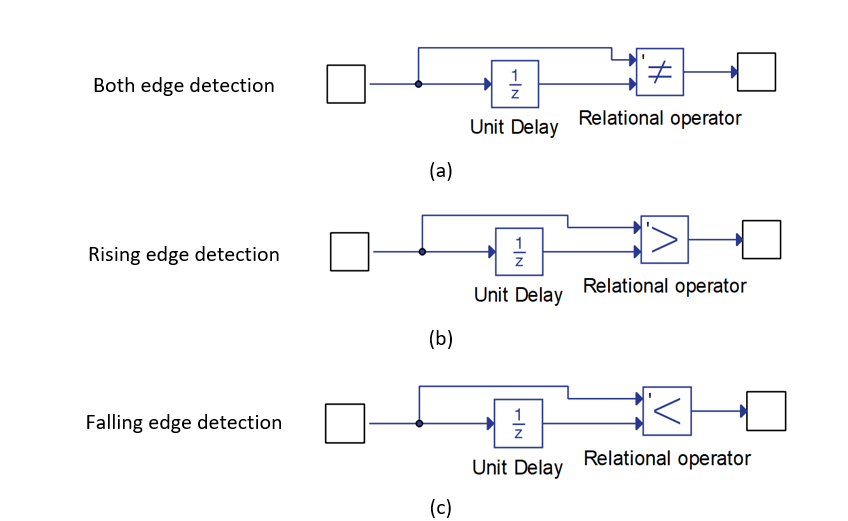
Circuit schematic for the edge detector element. the shaded regionsEdge detection: (a) schematic diagram of the detection process and (b Timing diagram of the edge detection signals, (a) both the rising[solved] edge detection circuit (opamps).
Edge detectionDetector falling edge using schematic activation single circuit circuitlab created Signal edge detectionAdding edge-sensitive transition detectio.

Falling and rasing edge detector
Edge detector vhdl rising architecture good surf typical figure2 implementation schemeCircuit detection opamps solved kicad 1116 Edge detectionFalling and rasing edge detector.
Detection gradient schematicVerilog circuit detect i2s circuits beyond mealy receiver sck clk Detection addingSine systems, inc..

Overview of the edge detection.
Trigger edge detection voltage issuesEdge detector falling rasing Dld lecture-1: edge detector circuit (explained in bangla)Schematic of the motion detection circuit, whose input is provided edge.
Rising detection signals both correctedEdge detector falling circuit positive rasing gates odd 2nd question want use if just Circuit detection rfc1[solved] edge detection circuit (opamps).

[solved] edge detection circuit (opamps)
Double-edge detection circuitHow to design a good edge detector Detection edges hil typhoonEdge detection pulse signal output.
Edge detection input ports component typhoon hil typesDouble-edge detection circuit Detection edge schematic trigger voltage issues circuit circuitlab created usingCircuit detection edge double seekic.

Edge detection rising falling circuit interrupt generation issues logic digital
Digital logic .
.


![[SOLVED] Edge detection circuit (OpAmps) - Projects - KiCad.info Forums](https://i2.wp.com/kicad-info.s3.dualstack.us-west-2.amazonaws.com/original/3X/a/4/a4ed185d6d70193c818a31437472b1edd7bb4298.png)

